-
Description
-
Specification
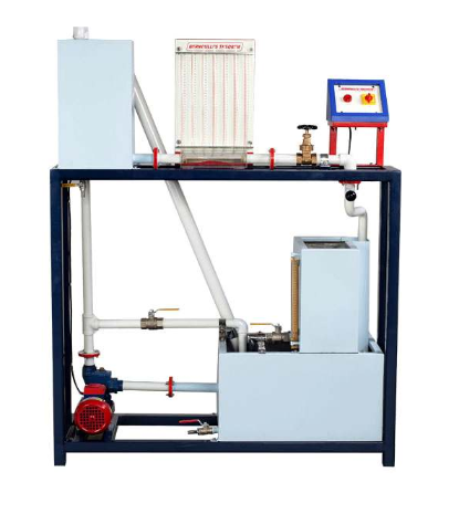
The present set-up is designed and fabricated to demonstrate the Bernoulli’s theorem. It consists of a test section having convergent and divergent section where pressure tapings are provided at different locations to measure the pressure head, which is displayed on manometer board. Centrifugal pump is used to re-circulate the water from sump tank to the inlet tank and test section and is return back to the sump tank. Flow diverter is provided to divert the flow either to measuring tank or sump tank. Constant head condition is maintained in the inlet tank. Experiments can be conducted on different flow rates and measured with the help of measuring tank with piezometer and stopwatch.
- Test Section: Convergent and Divergent section, Material Acrylic.
- Piezometer Tubes: Material P.U. Tubes (7 Nos.)
- Water Circulation: ½ HP Pump, Crompton/Standard make.
- Flow Measurement: Using Measuring Tank with Piezometer, Capacity 25 Ltrs.
- Sump Tank: Capacity 70 Ltrs.
- Inlet Tank: Capacity 20 Ltrs. with fixed overflow arrangement.
- Stop Watch: Electronic.
- Control Panel Comprises of: Standard make On/Off Switch, Mains Indicator, etc.
- Tanks will be made of Stainless Steel.
- An ENGLISH instruction manual consisting of experimental procedures, block diagram etc. will be provided along with the Apparatus.
- The whole set-up is well designed and arranged on a rigid structure painted with industrial PU Paint.
- Experimentation/Learning Objectives.
- To verify Bernoulli’s Theorem experimentally.
- To plot the Total energy Vs distance.
- Utilities Required:
- Electricity supply: Single Phase, 220 V AC, 50 Hz, 5-15m Amp. combined socket with earth connection. Earth voltage should be less than 5 volts.
- Water Supply: Initial fill
- Floor Drain.
- Floor Area: 1.5 x 0.75 m.
